Introduction
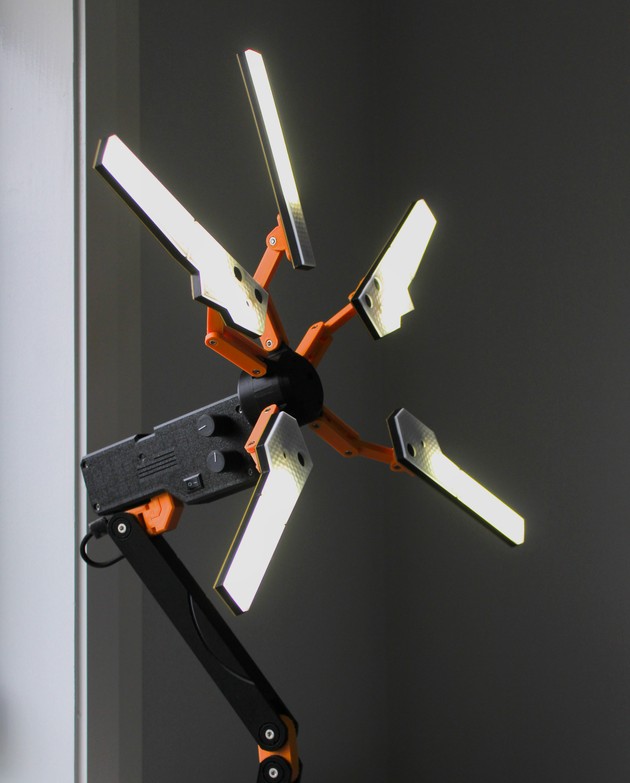
Death Stranding is an action-adventure game with some intriguing story and lore. An integral part of this is the Odradek terrain scanner, a futuristic piece of sci-fi equipment that facilitates some core game mechanics. Besides this, it also looks really cool. So when I found this incredible Odradek lamp build on Printables, I knew I had to build my own.
Since the 3D model files have been provided by the original creator of the lamp above, in this blog post I'll be focusing on my custom electrical design for the lamp, which consists of dimmable warm/cool white LEDs, with additional support for IR remote control.
Electronics
One of my core goals from the start was that the lamp had to be dimmable, and had adjustable colour temperature. This led to me choosing a 24v dual warm/cool white LED strip as the light source. For simplicity, PWM control was chosen to control the brightness of each channel. I chose the Arduino Nano as the microcontroller (since extra features such as Wi-Fi was not necessary).
Based on these requirements, I designed the following schematic.
Read on for an explanation of each of the different sections of the schematic. For pictures of the final circuit implementation of this schematic, see below.
LED Driver
I used a pair of IRLZ44N N-channel logic level MOSFETs to drive each LED channel. I also decided to use a dedicated MOSFET gate driver IC, the MC34152, since I wanted to use a high PWM frequency for the best light quality when dimming (to prevent any visible flickering). This has the additional benefit of reducing switching losses in the MOSFET by minimising the time it spends in the saturation region for each switching cycle.
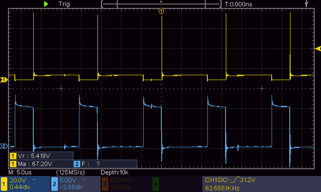
Using the maximum PWM frequency of the Arduino, 62.5kHz, the drain (CH1) and gate (CH2) waveforms of a MOSFET looks like this when switching the LEDs.

The ~67v voltage spike on the drain, which is caused by small stray inductances in the load, shows that the gate driver IC is doing it's job switching the MOSFET on and off very fast. The voltage spike should also pose no issues, as we can rely on the MOSFET's avalanche behaviour to clamp this voltage.
Additionally note that the MC34152 requires a decoupling capacitor placed close by to prevent instability in the supply rails. Since this IC is charging/discharging the MOSFET gates as fast as possible, it has large instantaneous current requirements.
Power Supply
I wanted the ability to power this device using USB C Power Delivery, which requires the 5-20V input to be boosted to 24V for the LEDs. Additionally, for the Arduino and the LED driver circuitry, a lower voltage level is necessary, so a small buck converter was used to get a 10V rail.
I would like to note that the power supply circuitry is non-ideal; the ON/OFF switch on the lamp doesn't actually disconnect power to the 24V boost converter, and the 10V buck converter being fed from the 24V boost converter output (which results in poor efficiency). This is because the use of USB C PD was a bit of an afterthought which required me to add the boost converter to the design to step up the USB C PD voltage. (The original plan was to use a dedicated 24V PSU.)
Brightness Control Inputs
I wanted to be able to set the light brightness using control knobs on the lamp, and also using a remote control (to control the lamp from a distance). For the control knobs, a pair of potentiometers were used, and to facilitate remote control, a simple IR receiver.
Sound 🔊
I decided to also add a buzzer to the design, which is always nice to include as it allows for the option of using sound to communicate information to the user.
Firmware
The firmware is available on this GitHub repo. I'll briefly cover the functionality here, but for detailed instructions on compiling and flashing this firmware yourself, see the readme file on the repo.
Overview
The main functionality of the firmware involves the Arduino continuously reading the potentiometer values and setting the PWM duty cycle for each LED channel based on this value.
The Arduino is also continuously waiting for signals from the IR remote control. When any IR code is received, the program switches from setting brightness from the potentiometers to instead using the data received from the remote control. In this mode, the brightness can be set independently of the value set on the potentiometers.
The input mode only switches back to the potentiometers if there is any change in the potentiometer inputs. This allows the lamp to be controlled using both the physical controls knobs and the remote control.
IR Functionality
The IR remote adds the following functionality:
- Power on/off
- Warm brightness up/down
- Cool brightness up/down
- Overall brightness up/down
- Setting brightness presets
Setting presets utilises the buzzer to provide audible feedback when the lamp is waiting for the user to select a slot, and when a preset has been set successfully. Preset brightness values are stored on the Arduino's built-in EEPROM, so they persist between power cycles.
3D Model Modifications
Since my design includes a few extra features compared to the original lamp, I had to make a few modifications to the original 3D models. Each of these modified files can be found at the downloads section below.
- Body enclosure left → New holes and mounting was required for the two brightness control potentiometers. Additionally, I used a smaller switch switch size of 15x10.5mm.
- Eye front → I replaced the hole for the blue LED with a small mounting slot for the IR receiver
I also had to tweak tolerances on the desk mount to body joint part. You may have to also manually fix tolerances for certain parts depending on your 3D printer.
Assembly
The assembly of the lamp went relatively smoothly since it was quite well designed. I was mostly able to follow the assembly instructions provided by the original creator.
Here are a few tips for the assembly process:
- The wiring channels to each of the light frames are quite small. Since I had to route 3 wires (Warm Anode, Cool Anode, Cathode), I used 0.4mm enamelled copper wire.
- Using a soldering iron makes inserting the nuts into the printed parts a lot easier.
- The tolerances on these parts are quite tight, so double check all your wiring before closing everything up.
Electronics Assembly
The driver circuit was implemented on perfboard (which was cut to size to fit inside the enclosure section of the lamp).

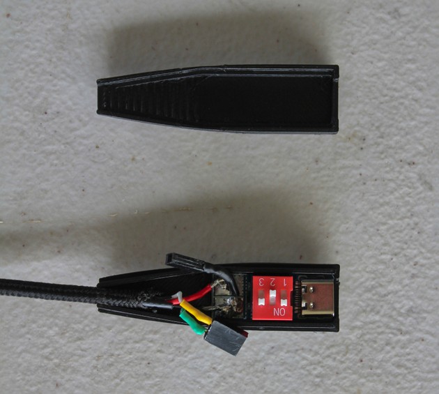
I used an old USB charging cable as the main power cable. I decided to repurpose the D+ and D- wires of the old cable to allow for reprogramming the Arduino Nano after closing everything up. As can be seen on the picture above, I desoldered the Mini USB connector from the Nano and soldered wires to the D+ and D- terminals.
The required reprogramming terminals (GND, D+, D-) can be accessed at this separate enclosure I designed to house the USB C PD trigger board.

Conclusion

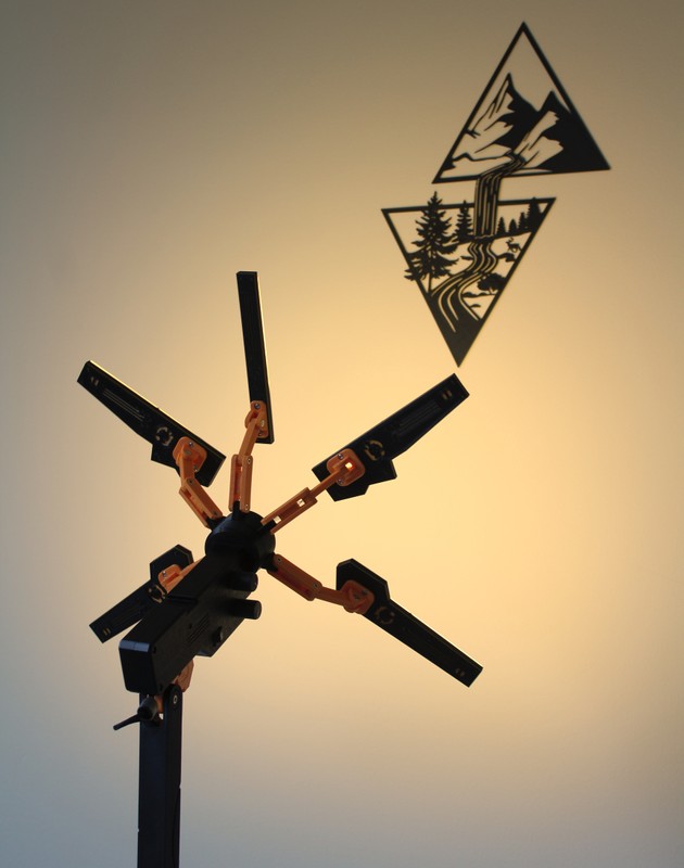
The final product turned out quite good, I'm particularly happy with the remote brightness and colour temperature control. Additionally, using USB C PD as the power source means I have the flexibility of also powering the lamp with a portable charger when needed.
Once again, massive thanks to @NilsKal on Printables for providing the 3D design of this lamp and making this build possible.
Links and Downloads
Links
- Original Desk Stranding Lamp Design by @NilsKal on Printables
- Firmware GitHub Repo
Purchase Links
- Warm/Cool White LED Strip → Aliexpress
- Micro Buck Converter → Amazon or Aliexpress
- Mini Boost Converter → Aliexpress
- USB C PD Trigger Board → Aliexpress
Downloads
- Modified Body Enclosure Left → body-left-modified.stl
- Modified Eye Front → eye-front-modified.stl
- USB C PD Trigger Board Enclosure → usb-pd-trigger-enclosure-top.stl, usb-pd-trigger-enclosure-bottom.stl, usb-pd-trigger-enclosure.step