Motivation
The Samsung Galaxy S5 was my first flagship smartphone. It was an impressive piece of technology for it's time, but it's been almost a decade since launching in 2014, and my S5 has spent quite a few years in a dusty drawer somewhere.
Reusing old tech is always nice because, best case, the energy used for recycling is conserved, or worst case, it stays out of landfill.
Introduction
Old phones can be used to make security cameras, home automation displays, etc. Smartphones are particularly useful because they are small, energy efficient computers attached to a whole suite of sensors.
One issue with running an old phone in a scenario like this where they would be plugged in 24/7, is the battery. Exposing Lithium batteries to heat over long periods usually causes them to swell up. In a tethered scenario, it's pretty likely you'd be doing something at least moderately computationally intensive, such as recording and broadcasting video, so heat is usually expected.
Since the phone will always be tethered, there is no real need for a battery. Unfortunately, most phones will not boot without a battery. This is probably for good reason, because the phone may sometimes draw more power than the USB charging port is able to provide.
Design Decisions
Battery Circuitry
Opening up the rear cover of the S5, we can remove the battery.

There are four contacts on the battery, with positive and negative labelled clearly. I'm not certain what the other two contacts of the battery are for (at least one of them is used for the NFC coil integrated into the battery). We do, however, need the connector between positive and negative. To summarise, here are the pins that we need to emulate the battery.

A 10kΩ resistor needs to be connected between the centre pin and the negative terminal, the phone will not boot properly without this resistor. Other resistor values may also work.
Voltage Source
The battery here is Lithium-ion, so we need a voltage in the range of 3.7v and 4.2v. To power the phone, we will need an external power adapter. However, an external power adapter that you can buy off the shelf will likely have voltages higher than 4.2v.
To deal with this, we will need to use a buck (step-down) DC-DC converter. To keep things nice and compact, I used a micro buck converter (purchase links below) that is small enough to directly integrate into the dummy battery structure that we will design next.
Dummy Battery Design
I 3D modelled the dummy battery in Fusion 360.

The dummy contacts will be 3 male pin headers, which can be pushed into position on the dummy battery after printing. I've also included some area on the design to fit the buck converter and circuit wires.
The next step is to 3D print the model. Since the dummy battery will be exposed to relatively high temperatures by the phone SOC and the buck converter, avoid printing this with PLA, use something more heat resistant such as PETG or ABS instead. I made the mistake of using PLA for my first version, and after a few days of use, the dummy battery was warped (which you can see on the images of the blue 3D print below), and the pins weren't making contact properly.
Assembly
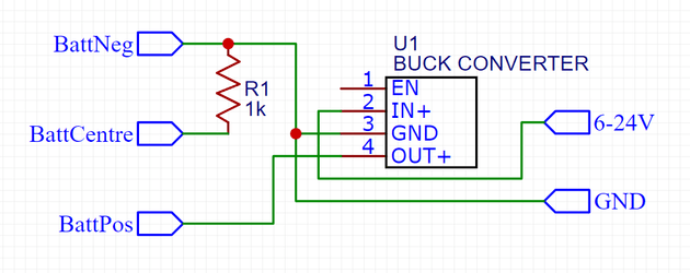
Here is the diagram for the circuit that we need to build.

I would recommend wiring up and testing the circuit beforehand. Don't forget to adjust the buck converter potentiometer until you have a voltage of ~4.2v on the output. Check that your circuit can reliably power the phone without causing brownouts (the camera app is a good way to test high current draw).
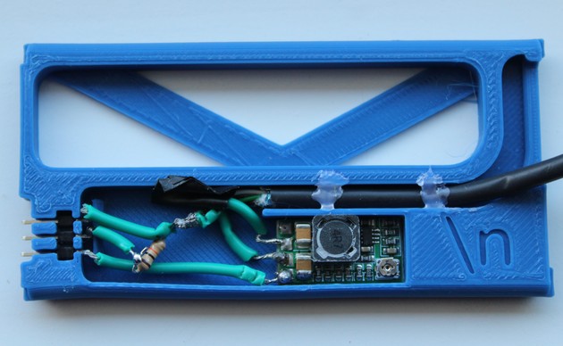
Soldering can be a little bit tricky, particularly for the male headers. These need to have wires soldered in a very specific way to make sure that the header can still be inserted into the slot on the 3D print, and such that the wires or solder don't intersect with the backstop. The backstop was added to prevent the header pins from sliding back
It's a good idea to solder with wires longer than you need, then trim to size later.
Here is what this circuit looks like assembled.

Final Notes
Supply Voltage
The buck converter used here should be able to step-down voltages between 6v and 24v. However, the converter will be less efficient at higher voltages, which results in higher temperatures. My buck converter reached ~75°C in open air when supplied with 24v during testing.
To avoid heat becoming an issue, choosing a supply voltage of around 12v should be optimal. Be careful choosing lower supply voltages such as 5v, as the voltage drop along longer power cables is sometimes enough to cause a brownout on the phone.
Also don't forget to make sure that the power supply you use can provide 15-20w of power, since the phone can have current spikes as high as 3A at 4.2v.
Deployment
After slotting in the dummy battery, the external power wire will likely mean that the rear cover of the phone will not go back on. This wasn't a deal breaker for me personally, because I used a case over the phone, and I routed the power wire around the side of the phone.
Links and Downloads
Downloads
- Dummy Battery 3D model → dummy_battery.stl, dummy_battery.step
Purchase Links
- Micro Buck Converter → Amazon or Aliexpress