Introduction
Colour e-ink displays are a relatively new technology that have become available to consumers in the last few years. E-ink displays are unique in that they are bistable, meaning they only consume power when the image displayed is changed. This makes them ideal for applications where the displayed image is static for long periods of time, such as e-readers. They also have the added benefit of working reflectively, increasing their visiblity as the level of ambient light increases.
The relatively recent commercial availability of these displays served as the inspiration for this project. Digital photo frames that utilise these displays already exist; however, these would only run for a few years on a single charge (which is, admittedly, still quite impressive). I wanted to build something that would run (effectively) indefinitely, keeping to the theme of what I think is the coolest feature of e-ink displays, their ability to retain a displayed image forever. As such, this project was designed from the ground up with a focus on longevity.
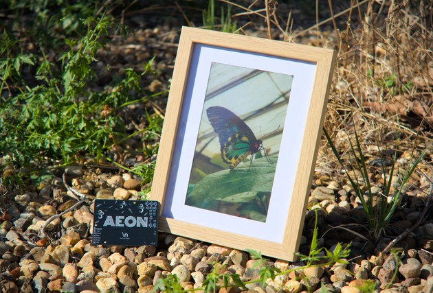
The final device should be indistinguishable from a normal photo frame, in both appearance and typical usage. That is, you should be able to treat it like a normal, static photo frame, and it should just work, ideally for an extended duration of time (think a decade or two). The only difference to a normal photo frame, the photo displayed will change maybe once a day, and to achieve this functionality, the device should never need to be charged.
Hardware
The central device that Aeon was designed around was the Waveshare 7.3" 7-colour e-ink display, chosen for its ability to display a range of colours, and its suitable size to fit in a 6x4 photo frame.
Since the final appearance of the device was important, all the electronics were required to fit within a fairly thin profile, which necessitated the use of a custom PCB.
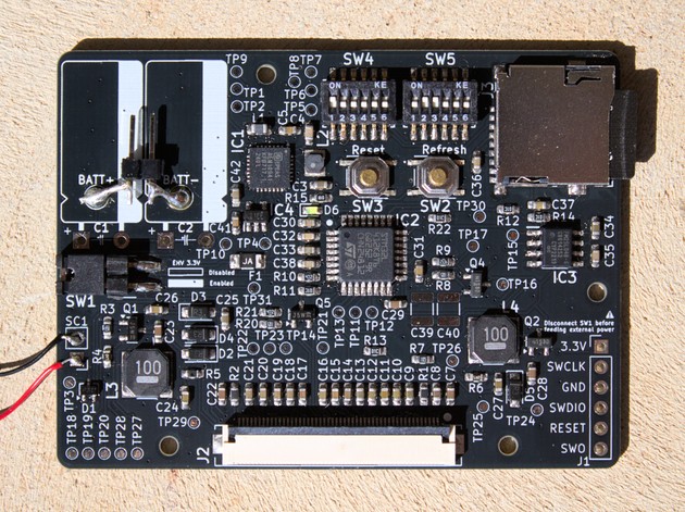
The main electronic systems on the PCB consist of the following:
- Power management: energy harvesting and storage, output regulation and voltage rail switching
- Processing: a low-power microcontroller to transfer image data from an SD card to the display, an FRAM IC to store configuration data
- Display driver: power circuitry for the e-ink display
Power System Architecture
The power system of Aeon was designed to be as efficient as possible, with the goal of minimising the quiescent current consumption of the device.
Energy Harvesting
One of the design goals for Aeon was continuous operation without the need for charging. This required finding a suitable ambient power source that could be harvested. Since the devices' power profile involves the majority of consumption ocurring when the image is changing, with near-zero power usage when displaying static image, the average power consumption should be very low.
In terms of energy sources for harvesting, light stands out as really the only option. The household environment that Aeon is intended to be used in does not have a particular abundance of other sources that can be harvested (e.g. heat, vibration, RF). Hence, light harvesting using solar cells was chosen for the design.
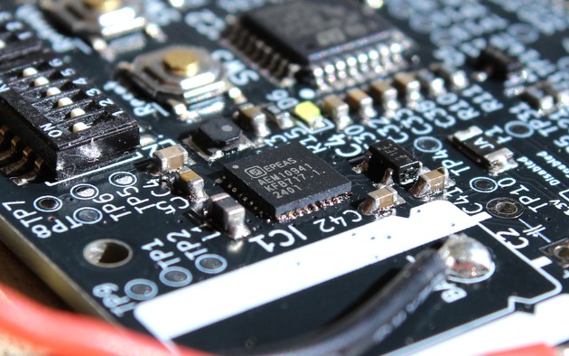
Aeon's power management circuitry is based around the E-peas AEM10941, an impressive little chip that integrates a basic MPPT controller with dual cascaded DC-DC converters to extract as much energy as possible out of the solar cells, even under poor lighting conditions.
Energy Storage
The choice of energy storage element was evaluated throughout the development process. I initially intended to use dual 6F supercapacitors to achieve the maximum longevity for the device, however, the energy storage to size ratio for these were quite poor. My calculations showed that a cold start would be required if the solar cells didn't see sun for even just a few days.
To avoid these issues, I went with a tiny 160mAh Li-ion battery instead. Under normal usage in a well-lit environment, this battery only sees very shallow charge-discharge cycles. Since Aeon doesn't rely on anything even close to the full 160mAh capacity of the battery (with a 24hr refresh cycle, it would run for months on a single charge), it would be reasonable to expect that the usable lifetime of the battery could last a decade or more.
Battery Protection
In the pursuit of absolutely minimising quiescent current consumption, I elected to remove the protection circuit of the Li-ion cell. Extreme care is needed during this process, accidentally shorting will cause even a tiny 160mAh cell to output 20+ amps of current, which can cause burns (ask me how I know). Additionally, extended shorting will permanently damage the cell and potentially cause thermal runaway.
So on the whole, I would recommend against this procedure, but I decided it was worth it to save a few microamps of current consumption. I tried to ensure that the features provided by the protection circuit would also be facilitated by the Aeon power management circuitry. I included a PPTC resettable fuse that should limit current in the unlikely event of some other failure on the board, and the AEM10941 directly protects against overcharge and overdischarge conditions.
Voltage Rails
The Aeon power architecture consists of two voltage rails, the main 3.3V rail is sourced by a low-quiescent current LDO voltage regulator, and is always active while the battery is within an acceptable voltage range. The microcontroller is powered by this main 3.3V rail. While the AEM10941 does include a built-in 3.3V regulator, it was not used because the display driver’s power requirements exceed the regulator’s current limit during refresh cycles.
The second voltage rail is an auxiliary 3.3V rail. This powers all the peripherals (SD card, FRAM IC, display driver). The auxiliary rail is manually enabled by the microcontroller through a P-channel MOSFET when a refresh cycle is initiated. This allows the peripherals to be completely powered off when not in use, minimising quiescent current consumption.
Processing
The brain of this project is the STM32L412K8 microcontroller.
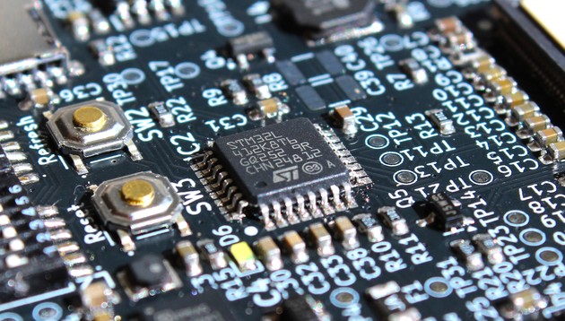
The selection criteria for this role was primarily minimal power consumption. The STM32L412 series has reasonably low power consumption when active, and, more importantly, has impressive low power modes. In the case of the STM32L412K8 used in Aeon, the IC theoretically consumes an incredibly low 0.2uA in standby mode, while allowing it to wake up from the internal RTC or an external signal.
This microcontroller handles interfacing with the SD card and the display, as well as scheduling RTC wakeups to ensure display refresh cycles occur at the configured intervals. Additionally, it monitors the battery voltage using the ADC and controls the auxiliary 3.3V rail, ensuring efficient power management. The STM32 communicates with all peripherals over SPI.
FRAM
A 4 Kbit FRAM IC is used to store configuration data. FRAM is a non-volatile memory technology that has the advantage of being able to be written to an effectively unlimited number of times, unlike EEPROM which has a limited number of write cycles. This IC is used to store various configuration data such as current image index, remaining sleep duration, etc.
Buttons and Switches
The PCB contains two buttons, one wakes the STM32 from standby and perform a manual refresh of the display, and the other is simply wired to the reset pin of the microcontroller.
Additionally, two 6x DIP switches are used to set configuration settings:
- ON/OFF switch for the device
- Enable/disable shuffling of images
- Refresh cycle duration in hours (configurable between 1 and 1024)
Display Driver
The display driver circuitry mainly consists of two DC-DC converters required to generate the necessary voltages for the display. These were not designed by me, but were taken from the reference design provided by Waveshare for this display.
Electronics Development
The Aeon schematic is shown below. For full design files, please see links at the end of this post.

This was the first custom PCB that I had designed, so there were several minor mistakes made. Additionally, due to time constraints, I worked on this project on-and-off over a few months; but these breaks worked out in my favour, as it gave me time to order new PCBs with bugfixes.
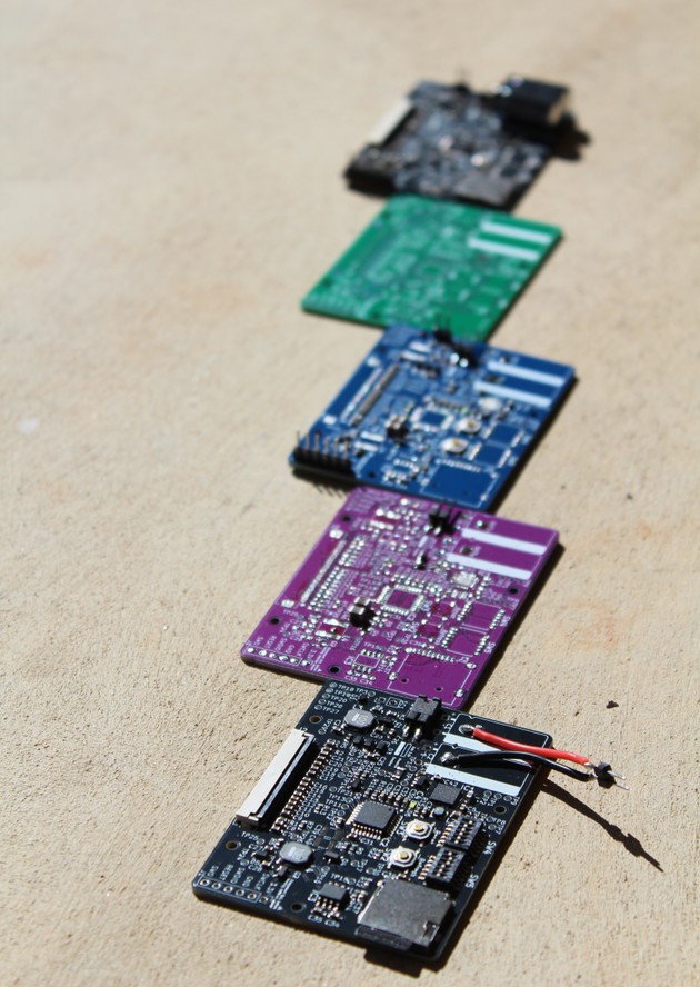
I went through five revisions. Several of these were semi-preventable by adding some bodge connections, but since I had the time, I decided to fix up any minor issues properly.
Frame Design
One of the key design goals for Aeon was that it should be indistinguishable from a normal photo frame. This meant the structure thickness had to be kept less than 8mm in order to fit in a standard 6x4 photo frame.
This constraint posed quite a few challenges during the design process, since this thin profile had to accommodate the PCB, the display, the solar cells, and the battery.
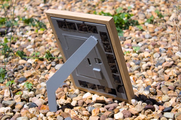
The design consists of a main body that the display, PCB and solar cells are mounted in, and a removable back cover that contains a slot for the battery. A back stand was also designed to emulate the functionality of a typical photo frame; however, its shape is slightly unconventional, designed to minimise the shadow cast on the solar cells.

Main Body Assembly
The parts were designed to be 3D printed, and as such, certain objects are printed in separate pieces that then need to be assembled by gluing together. Cyanoacrylate (superglue) was used for this purpose.
The far more substantial challenge was wiring and potting the solar cells. The solar cells are wired in series, and the wires are routed through the channel in the main body into the PCB area. The bare solar cells I used were incredibly thin and fragile. Soldering onto them is fairly difficult, flux is absolutely required to get the solder to flow onto the contacts on the cell. After wiring each one, they can be glued into the body using two small dabs of hot glue.
Once all the cells are glued in place, clear epoxy resin can be poured onto the inset area around the cells. This is a bit of a messy process, but it is necessary such that the device can be handled without worrying about damaging the solar cells.
I discovered the hard way that the resin can leak into the PCB area if the wiring channel is not properly sealed. Small amounts of epoxy can be carefully removed after curing using isopropyl alcohol and a scraping implement.
Final Assembly
The front side of the main body has an inset slot for the display to be placed into. For mounting, I simply used kapton tape on the rear of the display.
A paper mask was cut to size and placed between the display and the front glass to hide the display flex cable (for printable template, see links below). Once this is in place, the front becomes almost indistinguishable from a normal photo frame
The battery is attached onto the back cover using tape, and this cover can be slotted in to cover the PCB area of the main body. Finally, the removable back stand can be pushed into the slot on the back of the main body.
Software
The software for this project is split into two parts: the firmware running on the STM32 microcontroller, and the image conversion scripts.
Firmware
The firmware for the STM32 is generally quite straightforward. The basic logic that needs to be achieved is:
- Read next image from SD card
- Send image data to display
- Enter standby mode and set RTC wake interval for next refresh cycle
In practice, there is a bit more complexity to this. For example, the STM32L412K8 does not have enough RAM to store an entire image, so the image data is read from the SD card in chunks and sent to the display as it is read.
Additionally, the maximum RTC wake interval duration is around 18 hours, so the firmware needs to handle this limitation by chaining multiple wakeups together to achieve the desired refresh cycle duration. The FRAM is used for this chaining, and additionally for maintaining the current image index to allow the images to be changed in the desired sequence, even after a cold start.
Further logic is also present to monitor battery voltage, and to handle the various configuration settings that can be set using the DIP switches.
Image Conversion
The 7-colour e-ink display used cannot display images in the typical RGB format. Instead, images need to be converted such that each pixel is one of the 7 available colours. This conversion is done using a Python script that reads an image file and uses the Pillow library to perform the necessary dithering and colour mapping steps.
Additionally, Aeon requires images to be in a specific format to be displayed correctly. The microcontroller does not have enough resources to decode image formats like JPEG, so the SLIC format was chosen. This is a small and simple image format that was expressly designed for use in memory constrained embedded systems, while still providing a reasonable compression ratio.
The provided script handles all the necessary image conversion steps. The generated .slc files can be copied to the /images directory on the SD card.
Evaluation
Aeon was designed to be a set-and-forget device, and I'm happy with how close it came to this ideal. However, there are a few limitations that should be noted.
Energy Harvesting
One of the main limitations is the energy harvesting capability of the device. Rather, this was very informative experiment that showed how little energy is available for harvesting from indoor light sources. Initial designs had solar panels on the front of the device, but due to the inability to harvest enough energy (and since they would be visible and unsightly), these front panels were removed.
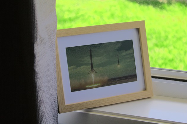
The final design relies on the solar cells on the back of the device, which means the device must be placed somewhere that receives outdoor light every so often. The device can run for months on a single charge, but if left in a dark room for an extended period of time, it will eventually run out of power. Somewhere such as a windowsill would be ideal. Direct sunlight is not necessary, even indirect light from outside is sufficient to keep the device running.
Overall, I'm satisfied with the low power consumption of the device. The quiescent current consumption of the device is <10uA (possibly even lower, I don't have the equipment to measure this accurately), meaning if the refresh interval is increased to longer than 24 hours, the device could stay functioning for a very long time even without any light.
Display Hardware
The e-ink display that was used has a few limitations.
The display takes around 30 seconds to refresh, which is quite slow. This is not a huge issue for a device that is intended to be set-and-forget, but since it takes a full minute to clear the screen and display a new image, the power consumption for a refresh cycle is quite high (in comparison to a B/W e-ink display, which would only take a few seconds to refresh).
Additionally, I wasn't able to achieve the advertised 800x480 resolution. The provided example firmware for the display writes 400x480 pixels of data (pixels on the display appear to be twice as wide as they are tall). This cuts the effective resolution in half, on a display that is already quite low resolution for its size. Update: this issue has been fixed!
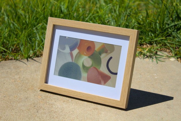
Lastly the colours of the display are quite muted. This is a limitation of the technology, however it does help the display appear more paper-like.
It would be interesting to create an equivalent device using a monochrome e-ink display, which have much better resolution and refresh speeds, given that they are a simpler and more mature display technology.
Final Thoughts
Aeon was a very fun project to work on, and I'm pretty happy with how it turned out. It gave me the opportunity to design a custom PCB, which was a great learning experience. Designing a power management system to target low quiescent current consumption was also quite interesting, I'm particularly looking forward to using the AEM10941 again in future projects.
The device is currently sitting on my windowsill, and I'm looking forward to seeing how long it will run for.
Links and Downloads
- Firmware, Image Conversion Scripts, and PCB Design Files → GitHub Repository
- Display Mask Template (A4) → aeon-display-mask-template.pdf
- 3D Design Files → aeon-frame-3d-design.step
Credits
The following resources were used in the creation of this project.
Software Credits
- SLIC image format library by bitbank2