Introduction
Input shaping/resonance compensation is the process that Klipper uses to minimise ringing/ghosting, which is a type of repeating artifact that appears on smooth surfaces of your prints, caused by the vibrations the printer creates as it moves (particularly as you start increasing print speeds).
To use input shaping with Klipper, you need to measure the resonance frequency of your printer. It's possible to do this manually, but it's a lot easier and reliable to use accelerometers to take these measurements for us instead. This post will go over this process.
For your reference, here is the Klipper documentation on measuring resonances.
Hardware
For most printers, only a single accelerometer is needed to measure both the X and Y axis. However, since the SV06 is a bed-slinger style printer, the extruder moves along the X axis, and the print bed moves along the Y axis. As such, it's necessary to use two accelerometers, one to measure each axis.
Using two accelerometers may pose some issues depending on the type of accelerometer that you use, as outlined in the Klipper docs. The documentation suggests connecting each accelerometer one at a time to do the measurements.
However, with a little creativity, you can get both accelerometers working simultaneously. The accelerometer I chose to use was the MPU6050, which uses the I2C bus to communicate. The RPi 3 (which is what I run my Klipper install on) does have a second I2C bus, but using it isn't as simple as the primary one. See this video if you are interested in going down this route.
Instead, the MPU6050 breakout boards that I used has an I2C Address Select pin (ADO), which, when pulled up to VCC, changes the I2C address of that accelerometer from 0x68 to 0x69. This lets us use both accelerometers on the same I2C bus.
Accelerometer Installation
Mounting
The next challenge is mounting the accelerometers to the extruder and the bed. My solution were the following mounts that can be 3D printed. Massive props to Sovol for making the SV06 Design Files available, which makes mods like this so much easier.
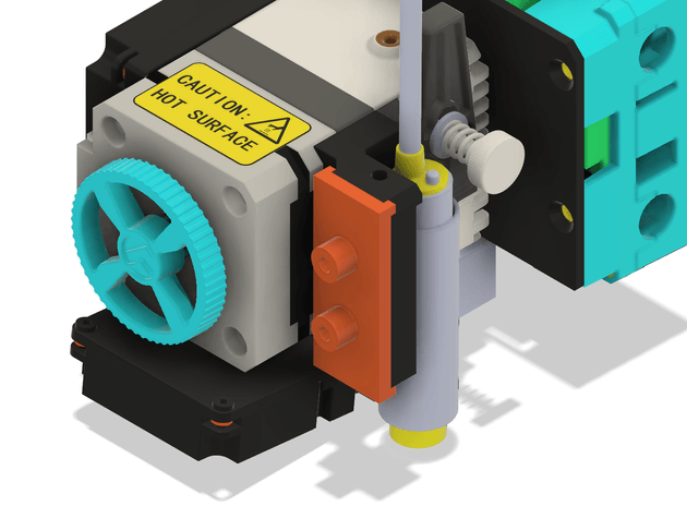
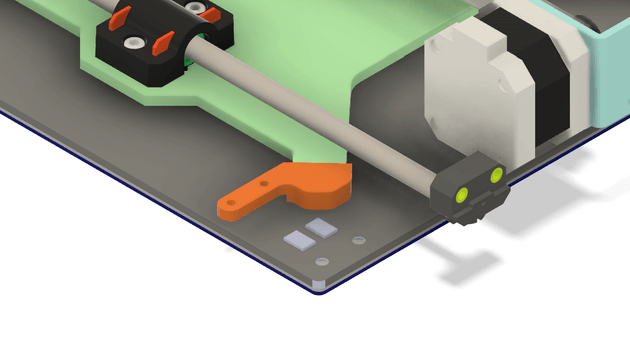
I recommend printing these parts in something like PETG rather than PLA, since they will be placed near heat-generating parts of the printer, and PLA might warp.
The MPU6050 boards screw into the mounts using M3 screws. The extruder mount is attached as follows, and secured using a cable tie.
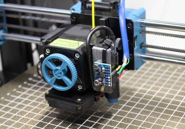
The print bed accelerometer is mounted as follows. As shown in the second image, use a cable tie to secure the mount onto the post.
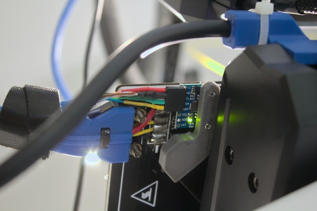
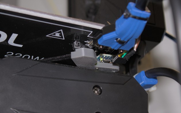
Warning: if you decide to keep the accelerometer wires installed permanently, they should be more securely cable managed.
Wiring
To wire I2C accelerometers to the RPi, Klipper documentation recommends using shielded ethernet cables.
The docs provide example wiring configurations for both two and three pair cables. Since ethernet cables typically come with four twisted pairs, I recommend the following configuration for optimal reliability.
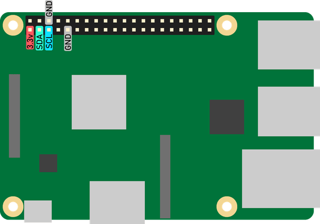
3.3V+GND
SDA+GND
SCL+GND
GND+GND
Create a wiring harness by cutting an old ethernet cable to size. I decided to make my wiring harness removable by adding female headers to both ends. Both accelerometers can be wired in parallel (don't forget to connect the ADO pin of one accelerometer to VCC).
Connect the wires to their corresponding connection pins on the Raspberry Pi (see the pinout below). Make sure to temporarily (or permanently) secure the wiring harness such that all axes can move to their full extents without interference.
Configuring Accelerometers
Firstly, you need to enable I2C on your RPi. Follow this section of Klipper docs to achieve that. After a restart, you can check whether the accelerometers are being detected properly by running the following commands.
sudo apt-get install i2c-tools
i2cdetect -y 1
You should see that positions 0x68 and 0x69 each have a device. If not, try restarting again. If it still doesn't work, there may be something wrong with your connections.
The next step is to tell Klipper to use the RPi GPIO as a microcontroller (because you would typically connect the accelerometers to a MCU, which you would then connect to the RPi). Follow Klipper docs here to set that up.
The final step is to add the accelerometers to the printer.cfg file. If you mounted your accelerometers with the same orientations as me, the following can be copied verbatim. Just remember to change the address of whichever MPU6050 whose ADO pin you pulled up to VCC.
#printer.cfg

[mcu rpi]
serial: /tmp/klipper_host_mcu

[mpu9250 extruder]
i2c_mcu: rpi
i2c_bus: i2c.1
i2c_address: 104 # This MPU has pin AD0 pulled low
axes_map: -x, y, z

[mpu9250 bed]
i2c_mcu: rpi
i2c_bus: i2c.1
i2c_address: 105 # This MPU has pin AD0 pulled high
axes_map: y, x, z

[resonance_tester]
# Assuming the typical setup of the bed slinger printer
accel_chip_x: mpu9250 extruder
accel_chip_y: mpu9250 bed
probe_points:
    100, 100, 20
If you mounted your accelerometers differently, you will need to work out how the axes of the accelerometer map to axes of the printer, follow the config reference here to determine your axes_map.
Validating
Finally, check that Klipper can read the accelerometers by entering the following commands into the Mainsail console.
ACCELEROMETER_QUERY CHIP=extruder
ACCELEROMETER_QUERY CHIP=bed
If everything is working, you should see the accelerometer readings printed out to the console.
Running Resonance Measurements
Start by installing the additional software dependencies required for the resonance measurements.
Once everything is installed, Follow these instructions to run the resonance measurements. Following the instructions here the first time, you will generate some cool graphs using the resonance data that you measure.
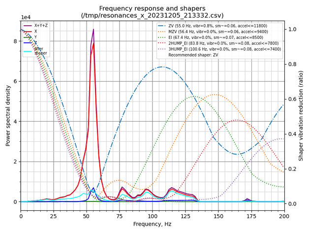
A resonance frequency of ~55Hz can be clearly seen on my printer's x-axis vibration graph above.
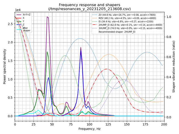
On the y-axis graph, vibrations of the bed (y-axis) has seemingly resulted in vibrations on both the y and z axes. This could actually be the bed movement inducing vibrations in the z-axis, or it could be due to poor accelerometer mounting, stemming from a poor mount design. Regardless, the resonances on the y and z axes lie at around the same frequencies, so the input shaping algorithm should work fine.
On subsequent runs, you can just use the command SHAPER_CALIBRATE to run calibration procedure for both axes automatically. It's worth noting that you should only run this procedure when you make any changes to the physical design of the printer, or move it to a new location, etc. Running resonance measurements regularly is not recommended, vibrations at the printer's resonance frequencies can be damaging.
Links and Downloads
Downloads
- Extruder Accelerometer Mount 3D Model → MPU6050_SV06_extruder_mount.stl, MPU6050_SV06_extruder_mount.step
- Bed Accelerometer Mount 3D Model → MPU6050_SV06_bed_mount.stl, MPU6050_SV06_bed_mount.step
Purchase Links
- MPU6050 Accelerometer Module → Amazon, Aliexpress